Select the machine from the mold drawing, not from maximum drilling depth alone. Use a three-axis drilling-and-milling center for straight holes from accessible faces, a dedicated horizontal gun drill for repeatable straight-hole production, and a five-axis platform for compound-angle channels or reduced reclamping. Confirm six values before quotation: mold dimensions and weight, material and hardness, hole diameter, hole depth, entry angle, and required tolerance. Representative HYM ranges extend from Ø1.5–40 mm on DM platforms and Ø3–60 mm on DH or AMD platforms, subject to model, tooling and workpiece conditions.
1. Calculate the depth-to-diameter ratio first
Divide drilling depth by finished hole diameter. A Ø10 mm hole drilled 600 mm deep has a 60:1 depth-to-diameter ratio, which makes entry guidance, coolant delivery and chip evacuation more important than nominal spindle power alone.
This ratio is a selection input, not a guaranteed capability. Material, straightness tolerance, tool system and whether the hole intersects another channel still have to be reviewed.
2. Choose the machine architecture from the hole direction
| Application condition | Recommended platform | Selection reason |
|---|---|---|
| Straight holes plus milling or tapping | DM three-axis drilling & milling | Combines gun drilling, twist drilling, U-drilling, milling and tapping in one setup. |
| Repeated straight-hole production | DH horizontal gun drilling | Dedicated horizontal layout supports stable coolant, guidance and chip removal. |
| Compound-angle or multi-face channels | AMD five-axis | Tilting and rotary positioning reduce manual reorientation of complex molds. |
| Unusually large, heavy or long molds | Custom system | Travels, table load, workholding and automation are defined from the part. |
Representative HYM DM platforms cover Ø1.5–40 mm gun drilling with depth options up to 1,300 mm depending on model. Representative DH and AMD data cover Ø3–60 mm, while the AMD-280 lists W-axis depth up to 1,600 mm and table-load options up to 25 t.
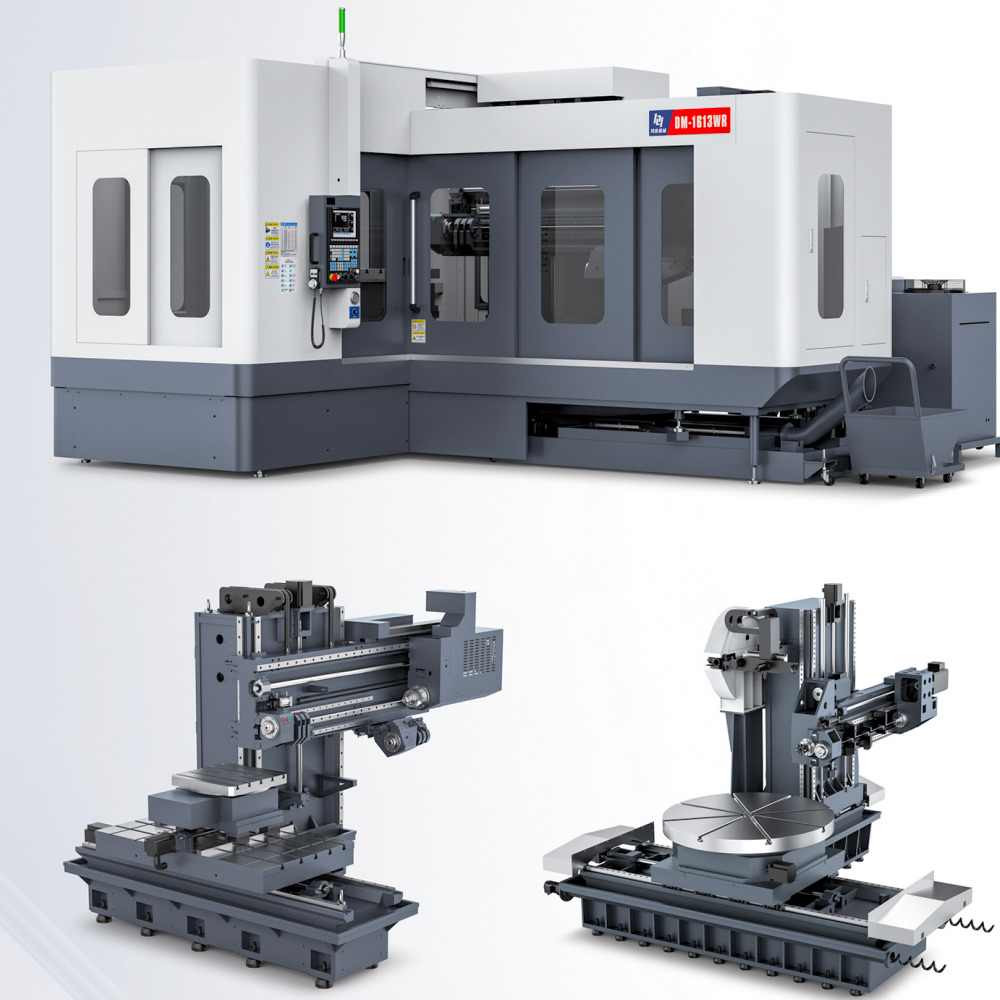
3. Match the work envelope to the complete mold
Compare the mold’s overall length, width, height and weight with usable travels, table area and permissible load. A drilling depth of 1,100 mm is irrelevant if the fixture and mold cannot fit inside the machine envelope or reach the planned entry face.
Allow space for fixtures, rotary devices and tool approach rather than comparing only bare-part dimensions. For reference, published DM-1300 data lists a 1,500 × 1,000 mm worktable and X/Y travels of 1,300/1,000 mm.
4. Define hole quality with measurable acceptance criteria
Specify diameter tolerance, straightness or exit deviation, surface roughness and intersection-burr acceptance. HYM representative process data lists H8–H11 hole accuracy and Ra ≤3.2 μm, but final results depend on material, tooling, parameters and machine configuration.
For cross-drilled cooling circuits, include a cleaning and pressure-test requirement in the FAT document. A channel that appears open may still contain chips or an intersection burr that restricts flow.
5. Evaluate coolant pressure, flow and filtration together
Pressure delivers coolant to the cutting zone, while flow transports heat and chips out of the bore. Representative HYM DM specifications list high-pressure coolant up to 100 kgf/cm², but the selected pump curve must match tool diameter and drilling conditions.
Ask the supplier to state filtration method, filter rating, oil-cooling arrangement and how pressure and flow are monitored. These four items affect tool life and process repeatability more directly than the maximum-pressure number alone.
6. Decide whether reducing setups creates enough value
A drilling-milling platform can replace separate drilling, milling and tapping setups when one mold requires several processes. The published DM process list contains five operations: gun drilling, twist drilling, U-drilling, milling and tapping.
A five-axis machine adds value when angled entries or multiple faces would otherwise require repeated manual setup. Calculate saved indicating, fixture and handling time per mold before comparing purchase prices.
7. Put the representative mold into the FAT
The factory acceptance test should use the customer’s actual material or a technically equivalent block. Record at least seven results: hole diameter, depth, straightness or exit position, roughness, cycle time, coolant condition and chip evacuation stability.
Also confirm machine configuration, control system, tooling list, fixture scope, electrical standard, documentation, training and after-sales boundaries. A signed FAT plan reduces ambiguity before shipment.
Buyer checklist
- Mold drawing, overall dimensions and weight.
- Material grade and hardness condition.
- Hole diameter, depth, direction and intersections.
- Diameter tolerance, straightness and roughness.
- Required milling, tapping or five-axis positioning.
- Annual mold quantity and target cycle time.
- Factory voltage, floor space and handling method.
Frequently asked questions
Which machine is suitable for straight mold cooling holes?
A DM three-axis drilling-and-milling center suits accessible straight holes when milling or tapping is also required. Representative DM data covers Ø1.5–40 mm and depths up to 1,300 mm depending on model.
When does a mold require a five-axis deep hole machine?
Use five-axis positioning for compound-angle cooling channels or when several mold faces must be reached with fewer reclampings. Representative AMD data covers Ø3–60 mm gun drilling and W-axis depth up to 1,600 mm depending on configuration.
Is maximum drilling depth enough to select a machine?
No. The supplier must also check part size, weight, entry direction, tooling clearance, fixture space, material, tolerance and production target.
What should be included in a quotation request?
Provide the drawing, material and hardness, hole geometry, quality requirement, annual quantity and desired cycle time. These six groups allow the supplier to recommend a defensible configuration.