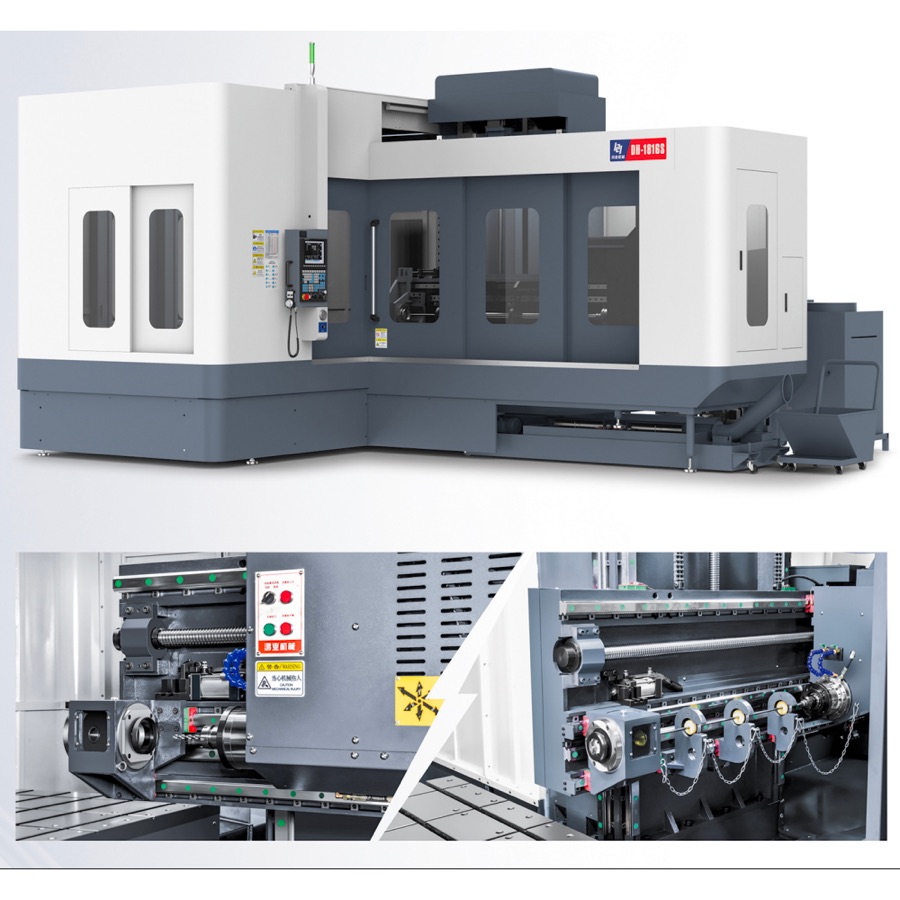
A deep hole drilling machine FAT should prove the signed specification with 12 recorded checks: machine identity, travel, positioning, spindle, coolant pressure and flow, filtration, chip evacuation, safety, representative cutting, hole quality, cycle time and documentation. Agree the workpiece, tool, material, measuring method and pass/fail limits before the test. For reference, published HYM configurations include drilling ranges of Ø1.5–40 mm on the DM platform and Ø3–60 mm on representative DH and AMD platforms; the FAT must use the limits of the purchased model, not a generic brochure.
1. Freeze the FAT scope before the machine runs
The FAT protocol should identify the purchased model, serial number, CNC, options and utilities. Record one approved configuration; representative HYM controls include FANUC or Syntec depending on the selected platform.
2. Use a representative workpiece and hole
Specify material, hardness, hole diameter, drilling depth, entry condition and tolerance before testing. A Ø10 × 600 mm test, for example, has a 60:1 depth-to-diameter ratio and should not be treated as equivalent to a shallow demonstration hole.
3. Confirm axis travel and usable work envelope
Measure commanded travel and check that fixtures, supports and tools fit inside the usable envelope. Representative published travel is 1,300/1,000 mm X/Y for the DM-1300 and 2,800/1,600/1,500 mm X/Y/Z for the AMD-280.
4. Verify positioning and repeatability
Agree the instrument, warm-up condition, measurement positions and acceptance limit. Representative DH-1600S data lists 0.025 mm positioning accuracy and 0.015 mm repeatability, while the purchased specification remains the governing limit.
5. Check spindle function under load
Run the drilling and machining spindles through the agreed speed range and record vibration, temperature or alarm results defined in the protocol. Representative DM-1300 and DH-1600S spindle data lists speeds up to 6,000 rpm.
6. Record coolant pressure and flow at the process
Pressure alone does not prove chip evacuation, so record both pressure and flow under the selected tool condition. Representative HYM DM and DH data lists maximum oil pressure up to 100 kgf/cm²; the required setting depends on tool diameter and process design.
7. Inspect filtration and temperature control
Confirm filter stages, cleanliness indication, oil cooling and alarm behavior while cutting. Record the installed filter specification because contaminated coolant can restrict small tool passages even when the pressure gauge reaches its target.
8. Prove chip evacuation through a complete hole
Observe chip form, return flow, load trend and interruptions over the full drilling depth. The test is complete only after the agreed hole depth is reached without an unapproved manual chip-clearing cycle.
9. Test guards, interlocks and alarms
Verify doors, emergency stops, pressure alarms, lubrication alarms and recovery procedures against the safety checklist. Record each test as pass or fail rather than relying on a general statement that the machine is safe.
10. Measure hole diameter, straightness and finish
Define instruments and measurement locations before drilling, then attach the report to the FAT record. Representative HYM DM process data lists H8–H11 hole accuracy and Ra ≤3.2 μm under suitable material, tooling and parameters; these figures are not universal acceptance limits.
11. Record cycle time with boundaries
State whether cycle time includes loading, tool approach, drilling, retract, inspection and unloading. Report both cutting time and total cycle time so the production estimate can be reproduced after installation.
12. Close every deviation and hand over evidence
List open items with an owner, corrective action and due date before signing. The final pack should contain the signed FAT, measured results, configuration list, manuals, diagrams, maintenance schedule and recommended spare parts.
| Area | Recorded evidence | Acceptance basis |
|---|---|---|
| Machine | Model, serial, CNC, options | Purchase specification |
| Motion | Travel and measurement report | Signed accuracy limits |
| Process | Tool, material, pressure, flow, cycle log | Approved test plan |
| Part | Diameter, depth, straightness, finish | Drawing and inspection plan |
| Handover | Signed report and technical documents | Contract document list |
Send the supplier one representative drawing and request a written FAT protocol before final machine assembly. This lets tooling, fixtures and measuring equipment be prepared before the acceptance date.
Frequently asked questions
What should be tested during a deep hole drilling machine FAT?
Test machine identity, axis travel, positioning, spindle, coolant pressure and flow, filtration, chip removal, safety, a representative drilling cycle, hole quality, cycle time and documentation against the signed specification.
Should the FAT use the buyer's workpiece?
Yes. Use a representative workpiece or an agreed test coupon with the specified material, hole diameter, depth, tolerance and tooling so that the result is relevant to production.
How is a FAT acceptance limit defined?
Write the measurement method, instrument, sample quantity and pass/fail limit into the FAT protocol before testing. A machine brochure alone is not an acceptance protocol.
Which documents should be supplied after FAT?
The agreed package should include the signed FAT record, machine configuration, electrical and hydraulic diagrams, manuals, maintenance schedule, recommended spare parts and measured test results.
Still defining the machine itself? Read how to select a deep hole drilling machine for mold cooling holes, then use this FAT checklist to convert the selected configuration into measurable acceptance evidence.