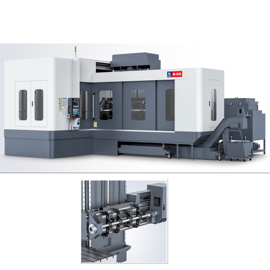
Do not compare deep hole drilling machines using feed rate alone. Calculate cutting time from actual tool travel and programmed feed, then add approach, retract, indexing, tool change, probing, chip clearing and other automatic motions. Report setup and operator time separately, and apply an agreed utilization factor before converting cycle time into annual capacity. Require the supplier to demonstrate the calculation during FAT using the agreed material, hole diameter, depth, tooling and quality limits. A transparent time study identifies every assumption and prevents a theoretical cutting-time figure from being mistaken for finished-part output.
1. Calculate theoretical cutting time first
For constant programmed feed, divide cutting travel by feed rate. A 600 mm travel at 60 mm/min equals 10 minutes of theoretical cutting time.
600 mm ÷ 60 mm/min = 10 min. This arithmetic example is not a recommended parameter for a particular material or tool.
2. Use tool travel, not nominal hole depth alone
Include approach, engagement and agreed breakthrough allowance in the calculation. If total programmed travel is 620 mm rather than a 600 mm finished depth, use 620 mm in the time model.
3. Add every automatic non-cutting motion
Record approach, retract, tool change, indexing, probing and chip-clearing time as separate lines. These 6 categories make quotation comparisons auditable.
4. Separate automatic cycle time from manual time
Automatic cycle time ends when the programmed sequence finishes, while loading, alignment, inspection and unloading require separate labor assumptions. Report at least 2 totals: machine automatic time and operator-attended time.
5. Calculate time per hole and per finished part
Multiply the verified time for each hole type by its quantity, then add shared indexing and handling time once. Four identical 12-minute hole cycles equal 48 minutes before shared motions are added.
6. Account for integrated milling and tapping
A drilling-milling platform may complete several operations in one setup, so the comparison must include removed transfers and reclamping. Representative HYM DM machines support 5 process groups: gun drilling, twist drilling, U-drilling, milling and tapping.
7. Convert scheduled hours into available minutes
Multiply scheduled production hours by 60, then apply the agreed utilization assumption. One 8-hour shift provides 480 scheduled minutes before planned stops, setup and maintenance are deducted.
8. Keep the utilization factor visible
Capacity changes directly with the utilization assumption, so never hide it inside the final result. At an illustrative 75% factor, 480 scheduled minutes become 360 available minutes; buyers must replace this example with their own documented value.
9. Calculate daily capacity from demonstrated cycle time
Divide available minutes by complete cycle time and state whether partial units are counted. At 360 available minutes and a 60-minute cycle, the arithmetic result is 6 parts per shift.
10. Build annual capacity from the production calendar
Multiply complete parts per shift by shifts per day and planned production days. Six parts × 2 shifts × 250 days equals 3,000 parts per year before product-mix or demand adjustments.
11. Run sensitivity checks on the largest assumptions
Recalculate output at alternative utilization, setup and tool-change values instead of publishing one number. Comparing 3 scenarios—conservative, expected and upper bound—shows how robust the purchase case is.
12. Verify cycle time and quality in the same FAT run
Record material, tool, hole diameter, depth, feed program, start point, finish point and measured quality. These 8 evidence fields connect the timing result to an accepted process rather than an empty-machine motion test.
| Time element | Required input | Verification |
|---|---|---|
| Cutting | Travel, programmed feed and process segments | Program and timed representative cut |
| Automatic motions | Approach, retract, index, tool change, probing | Complete automatic cycle |
| Manual work | Load, align, inspect and unload method | Separate observed labor time |
| Capacity | Schedule, utilization and product mix | Buyer-approved calculation sheet |
| Quality | Diameter, depth, straightness and roughness limits | Measured FAT results |
Send one part drawing, material, hole table, annual quantity and target shift pattern. These 5 input groups allow HYM to prepare a traceable machine and cycle-time proposal.
Frequently asked questions
How is deep hole drilling cutting time calculated?
For a constant programmed feed, divide cutting travel in millimetres by feed in millimetres per minute. Add approach, breakthrough allowance and any programmed dwell or peck segments used in the approved process.
Is cutting time the same as machine cycle time?
No. Machine cycle time also includes approach, retract, tool change, indexing, probing, chip clearing and other automatic motions; labor and setup time should be reported separately.
How should annual machine capacity be estimated?
Multiply scheduled hours by an agreed utilization factor, convert to available minutes, and divide by demonstrated cycle time. Keep setup, maintenance and product-mix assumptions visible.
How should cycle time be verified during FAT?
Run the agreed material, tool, hole diameter, depth and quality requirement, then record start and finish points, automatic cycle time, manual time and measured hole results.
Use the machine FAT checklist to define timing evidence, review the maintenance checklist when setting utilization, and compare HYM deep hole drilling machine platforms.