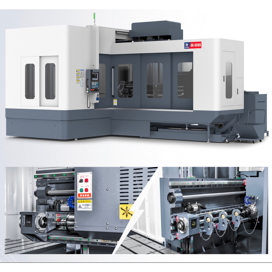
Do not select a gun drilling coolant system from maximum pressure alone. The quotation should state the pump operating point, adjustable pressure and delivered flow for the proposed tool, followed by filter stages, tank capacity, temperature control, gauges and alarm logic. During FAT, record pressure and flow while drilling the agreed diameter and depth, then inspect chip evacuation, coolant cleanliness, temperature stability and hole quality. Representative HYM DM-1300 and DH-1600S data lists maximum oil pressure up to 100 kgf/cm²; this is a system limit, not the correct setting for every tool.
1. Pressure and flow perform different jobs
Pressure overcomes restriction and delivers coolant through the tool, while flow carries heat and chips back through the flute. A specification containing only “100 kgf/cm² maximum” provides 1 pressure limit but no delivered-flow evidence.
2. Compare the pump at its operating point
Ask for pressure and flow at the same operating condition because pump flow can change as system pressure rises. The quotation should contain at least 2 linked values—pressure and flow—rather than two unrelated maxima.
3. Calculate flow from measured volume and time
A simple FAT check divides collected coolant volume by elapsed time: 20 litres collected in 2 minutes equals 10 L/min. Use an agreed safe measurement method and compare the result with the signed pump operating point.
20 L ÷ 2 min = 10 L/min. This example demonstrates the calculation and is not a recommended flow for a particular gun drill.
4. Match the system to the proposed hole range
Small tool passages and larger chip loads do not impose the same coolant requirement. Representative HYM ranges span Ø1.5–40 mm on the DM platform and Ø3–60 mm on DH and AMD reference configurations, so one fixed setting cannot cover every diameter.
5. Put filter stages and rating into the quotation
Request the number of filtration stages, filter-media rating and the measurement basis used by the supplier. These 3 items are more auditable than a statement such as “high-precision filtration” without a numeric rating.
6. Check differential pressure and filter alarms
A filter can restrict supply as contamination builds, even when the pump remains operational. The FAT should verify at least 2 conditions: normal indication and the agreed blocked-filter alarm or maintenance threshold.
7. Inspect chip return over the full depth
Observe return flow, chip form and load trend from entry to final depth rather than during a short demonstration. A 600 mm-deep Ø10 mm hole has a 60:1 depth-to-diameter ratio, making full-depth evacuation evidence materially more useful than a shallow cut.
8. Define temperature-control evidence
Record coolant temperature at the start and end of the agreed cycle and define the permitted change before testing. Representative HYM DM and DH configurations include oil cooling, but the purchased model and FAT limit must be stated in the order documents.
9. Confirm tank, return and cleaning access
The buyer should review 3 physical areas: clean-oil supply, dirty-oil return and access for removing settled chips. Tank capacity must be evaluated with the pump flow, heat input and production cycle rather than as an isolated litre value.
10. Include gauges, sensors and data units
Pressure and flow readings should identify location, range and unit so results can be repeated after installation. Record at least 4 fields for each reading: instrument, measurement point, value and pass/fail limit.
11. Run the coolant system during representative cutting
The FAT should use the agreed tool, material, hole diameter and depth; these are 4 minimum process inputs. Check pressure, flow, temperature, chip evacuation and alarms during the same cycle used to measure hole quality.
12. Retain a reproducible coolant record
The final record should contain the pump configuration, filter elements, oil specification, operating values and maintenance intervals. Keeping these 5 groups with the signed FAT gives the installation team a usable baseline.
| Area | Quotation evidence | FAT evidence |
|---|---|---|
| Pressure | Adjustable range and system maximum | Reading during the agreed hole |
| Flow | Delivered flow at operating pressure | Measured value and method |
| Filtration | Stages, rating and media | Cleanliness, indication and alarm test |
| Temperature | Cooling method and control scope | Start/end readings and acceptance limit |
| Maintenance | Elements, intervals and access | Documented baseline and spare list |
Send the supplier one representative hole and request a coolant-system schedule showing pressure, flow, filter stages, rating, tank, cooling and instruments. This turns 7 purchasing questions into a comparable technical offer.
Frequently asked questions
Is maximum coolant pressure enough to select a gun drilling machine?
No. The supplier must size pressure and flow for the tool and verify the complete circuit under cutting conditions, including filtration, temperature control and chip return.
What coolant data should be included in a machine quotation?
Request the pump operating point, adjustable pressure range, delivered flow, filter stages and rating, tank capacity, temperature-control method, monitoring points and alarm logic.
How should coolant performance be checked during FAT?
Record pressure and flow while drilling the agreed hole, inspect chip evacuation and coolant condition, verify alarms, and compare temperature and hole-quality results with the signed FAT limits.
What pressure is listed for representative HYM machines?
Representative HYM DM-1300 and DH-1600S published specifications list maximum oil pressure up to 100 kgf/cm². Final settings depend on model, tool diameter, material and process.
For procurement sequencing, first review machine selection for mold cooling holes, then use the 12-point FAT checklist to define measurable acceptance evidence.