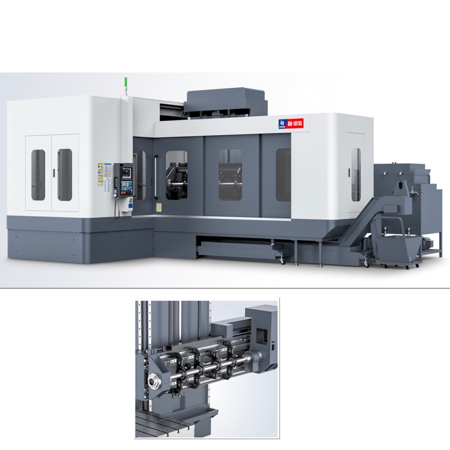
Specify the gun drilling fixture from the workpiece datum scheme, hole direction, part mass, unsupported span and loading method—not from machine travel alone. The fixture must locate the part repeatably, resist drilling thrust without distortion, align the entry guide to the spindle, seal coolant where required and leave a clear path for chips and measurement. Put the ordered fixture into FAT with a representative part and record setup, clamping, entry alignment and hole results. A fixture is process equipment, so its drawings, change parts and acceptance limits belong in the purchase specification.
1. Freeze the datum scheme before fixture design
Mark the primary, secondary and tertiary datums on the approved drawing. These 3 datum levels define how the part is constrained and how hole position will be measured.
2. Record the complete loading condition
State part dimensions, mass, center of gravity and whether loading is manual, crane-assisted or automated. These 4 values determine access, lifting points and safe support placement.
3. Calculate the unsupported span
Measure the distance between effective supports rather than quoting overall part length. For a shaft supported at two points 1,200 mm apart, the design span is 1,200 mm even when the complete shaft is longer.
4. Separate location from clamping
Locators establish position while clamps maintain contact against cutting and handling forces. Document at least 2 functions for every element so a clamp is not incorrectly used as the only datum.
5. Define entry-guide alignment
Specify the guide-bush or entry-support position relative to the spindle axis and workpiece datum. FAT should record 1 agreed alignment method, its instrument and its pass-fail limit before drilling.
6. Check clamping force against part distortion
More force is not automatically safer on thin walls, tubes or finished surfaces. Require 2 checks: the part remains seated during cutting and released-part dimensions remain within the drawing limits.
7. Plan support for shafts and round bars
Long cylindrical parts may require steady rests, V-blocks or driven support depending on rotation and drilling direction. List every supported diameter and change part; a fixture covering 3 diameters should have three documented settings.
8. Protect coolant sealing and chip clearance
Show seals, drains, chip exits and access for cleaning in the fixture drawing. Review 4 paths—coolant supply, coolant return, chip evacuation and service access—before approval.
9. Verify tool and machine clearance
Check the fixture through approach, full drilling depth, retract, indexing and loading positions. A minimum of 5 machine states should be reviewed in layout or simulation to prevent collisions.
10. Put repeatability and hole quality into FAT
Load and unload the representative part for the agreed sample quantity, then measure datum repeatability and the specified hole results. Record at least 6 evidence fields: setup identity, clamp state, entry alignment, diameter, depth and straightness or exit position.
| Area | Design evidence | FAT evidence |
|---|---|---|
| Datums | Drawing and locator scheme | Measured setup repeatability |
| Support | Span, mass and support positions | Stable representative cut |
| Clamping | Sequence and contact locations | No movement or distortion |
| Process | Guide, coolant and chip paths | Full-depth drilling record |
| Handover | Drawings, parts list and settings | Signed setup and training record |
Frequently asked questions
What information is needed to design a gun drilling fixture?
Provide the part drawing, datum scheme, material and hardness, part mass, hole diameter, depth and direction, tolerance, annual volume, loading method and any required rotation or indexing.
Why is intermediate support important for long shafts?
Support limits workpiece deflection and vibration over the unsupported span. The number and position must be engineered from shaft diameter, length, mass, clamping and rotation conditions.
Should the fixture be included in FAT?
Yes. FAT should use the ordered fixture and agreed representative part, then record loading, clamping, datum repeatability, tool entry, coolant sealing, chip clearance and measured hole results.
Can one fixture cover several part variants?
Yes when the datum scheme, adjustment range and change parts are documented. Each supported variant should be listed with its setup method and acceptance checks.
Review HYM horizontal gun drilling machines, combine the fixture checks with the machine FAT checklist, and verify coolant requirements in the coolant specification guide.